'P' is for Printer - or vocabulary of 3d printing
Nobody can help you if you cannot explain what is wrong. In the same spirit, it is much easier to reason about things once you give them names. In this article, I introduce the basic concepts and terminology used in 3D printing.
Nobody can help you if you cannot explain what is wrong. In the same spirit, it is much easier to reason about something once you can name its parts.
This article is not an advanced printing guide, nor is it really a guide at all. It is a vocabulary for people who have just bought a printer and are trying to understand what everyone is talking about.
Overview
To make it simple, I’ve divided our vocabulary into three areas:
-
Software — the programs and file formats used to design a model, prepare it for printing, and control the printer.
-
Hardware — the physical components of the printer, the materials it uses, and the profiles that describe them.
-
Printing — the decisions involved in turning a model into a successful physical object, including walls, infill, supports, and bed adhesion.
So this doesn’t read like a dictionary, I’ll drag one object through all three: a small connector I designed in Fusion — a profile with two notches and a bit of texture.
The complete journey looks roughly like this:
The connector’s journey
A pencil sketch on graph paper: the top half, mirrored down, every size written on it.
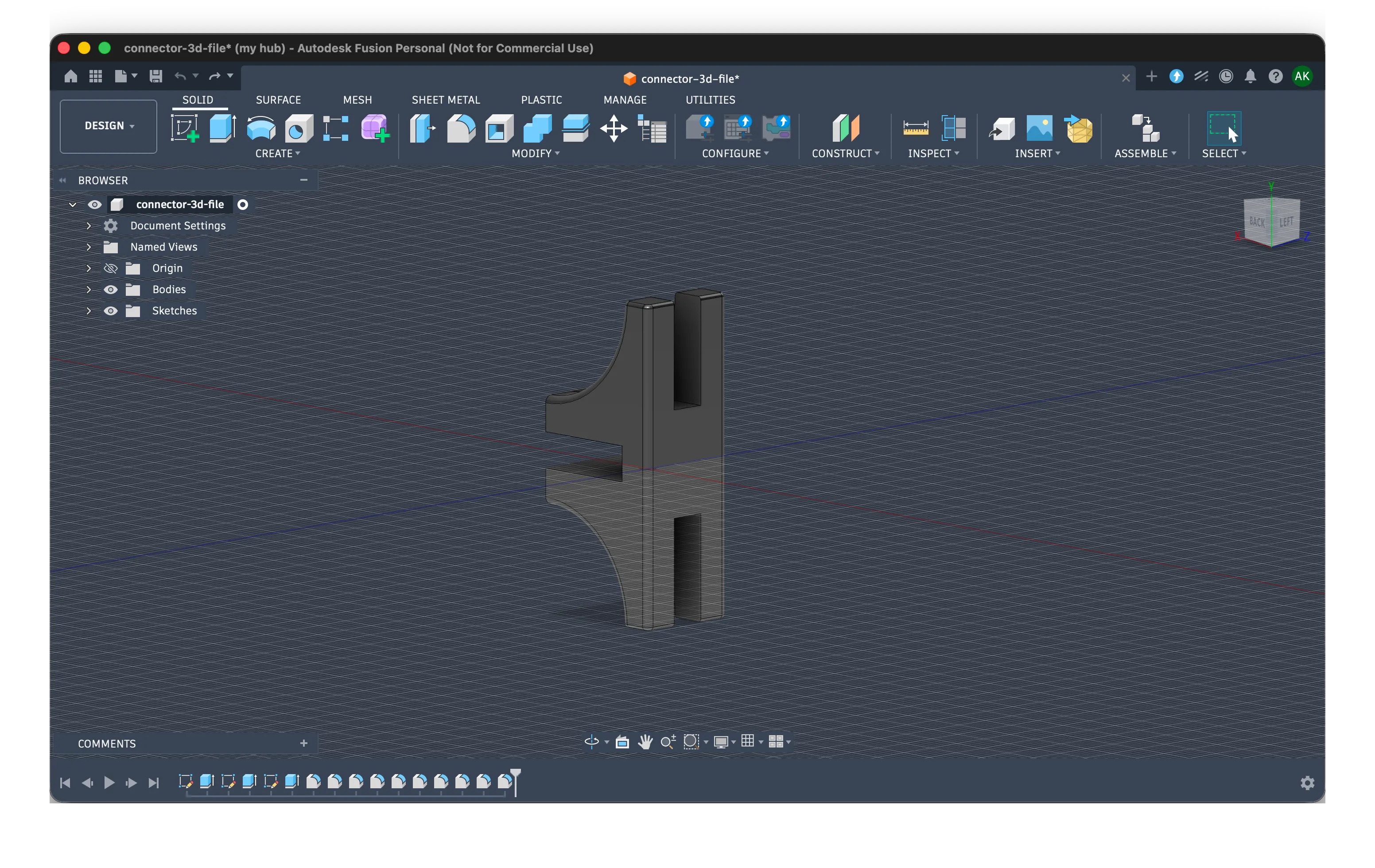
Fusion extrudes the profile 15 mm and cuts two notches (connector.f3d), then it leaves as model.stl and gets its texture in bumpmesh.
Takes the .stl / .3mf and cuts it into 75 layers of 0.20 mm.
Every layer becomes a list of moves: connector.gcode.
Reads the moves line by line and turns millimetres into motor steps.
20 × 45 × 15 mm of PLA on the bed.
75 layers of 0.2 mm. The notches are the short ones.
Let us begin with the software.
Software
My first goal was simple: find a small object online and print it. My second was to make my own part.
Somewhere in between I discovered there is no single “3D printing program.” It’s a relay race, and each program carries the baton for one stage.
CAD
CAD stands for computer-aided design. This is the tool you use to design a model. And really there’s not much to it.
Honestly you can skip this step for your first prints and just get ready models from a plethora of specialized sites.
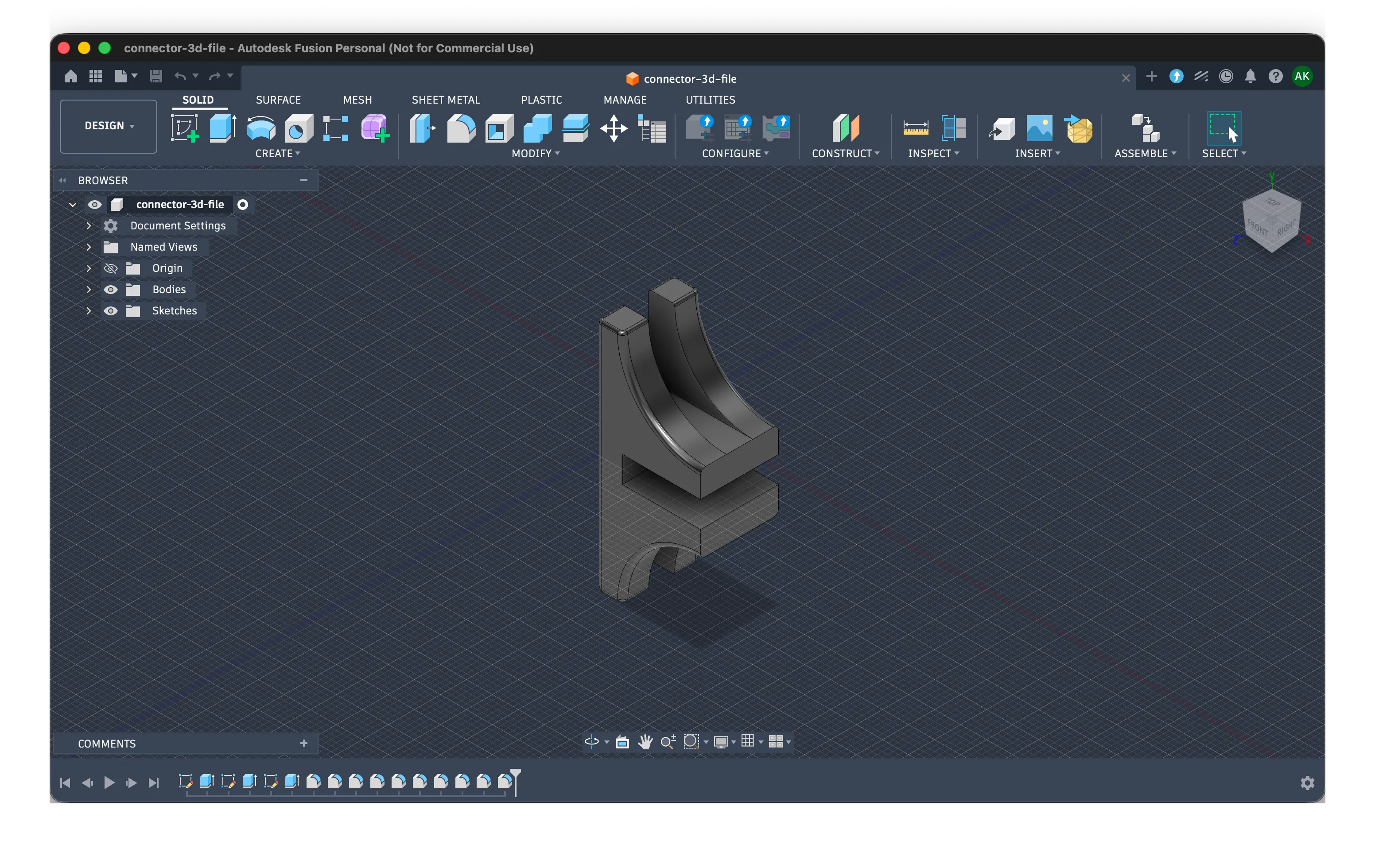
If however there comes a point you need to design a custom piece I suggest you don’t agonize over the tool choice like some people do with linux distros and just use fusion360. Really, it’s free, it’s professional and it will set correct examples and patterns for you. It will make you think about model design in terms of measurements, constraints and patterns and ensure you will never need to relearn.
Working with fusion360
There are plenty of guides, even autodesk has a nice one. But I always find it easier to understand the macro before jumping into implementation.
Work in Fusion is split into two phases: sketching and modeling.
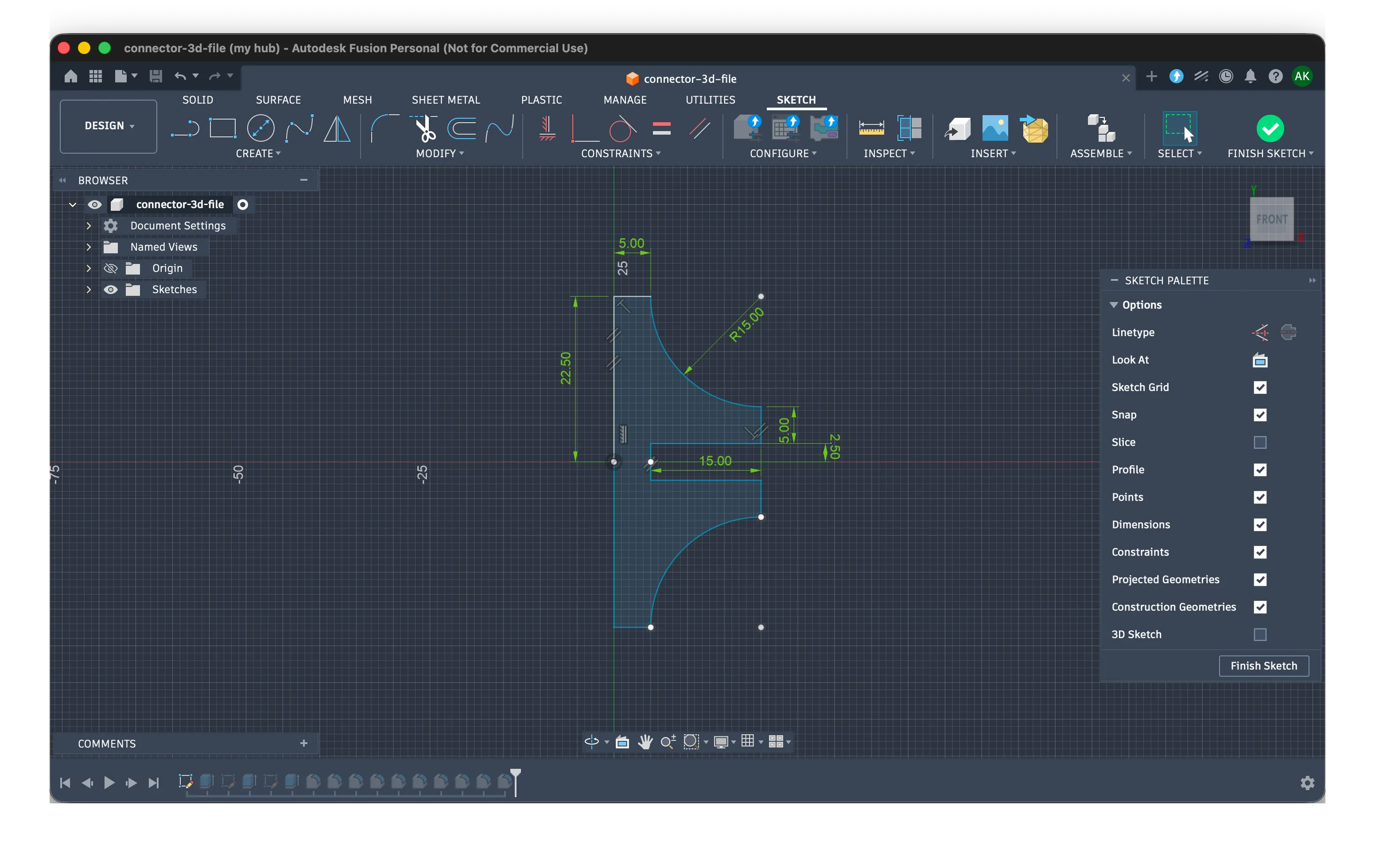
In the sketch phase you draw your shape, think of this as the 2D projection of your future model. If you look closely you’ll see that mine is centered at the origin, this is because I only drew the top part and mirrored it down. You will also notice measurements in green defining exactly how big each of the parts is. And lastly there are constraints.
If you remember basic geometry these will look familiar - perpendicular, parallel, equal.
You will quickly find that building a model includes lots of tweaks, the more complex the model the more your tweaks can break it. Constraints help keep the model in check.
For example if I define two lines as equal, changing one automatically changes the other.
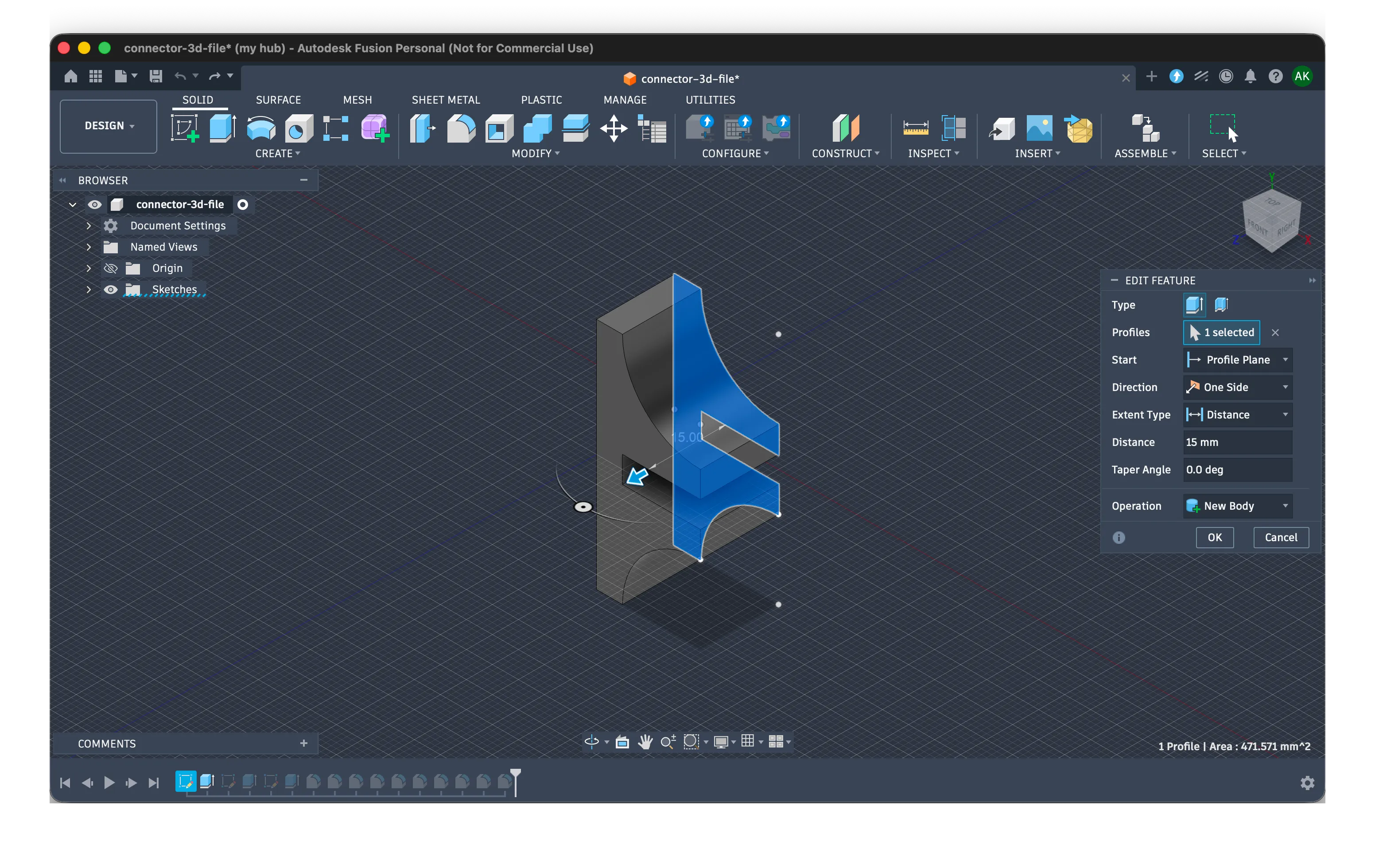
Once you’re done with the basic shape you can proceed to the next step - extruding or modeling - that is, adding the 3rd dimension.
This step is fairly trivial in my case - I just add 15mm width to the model. Voilà!
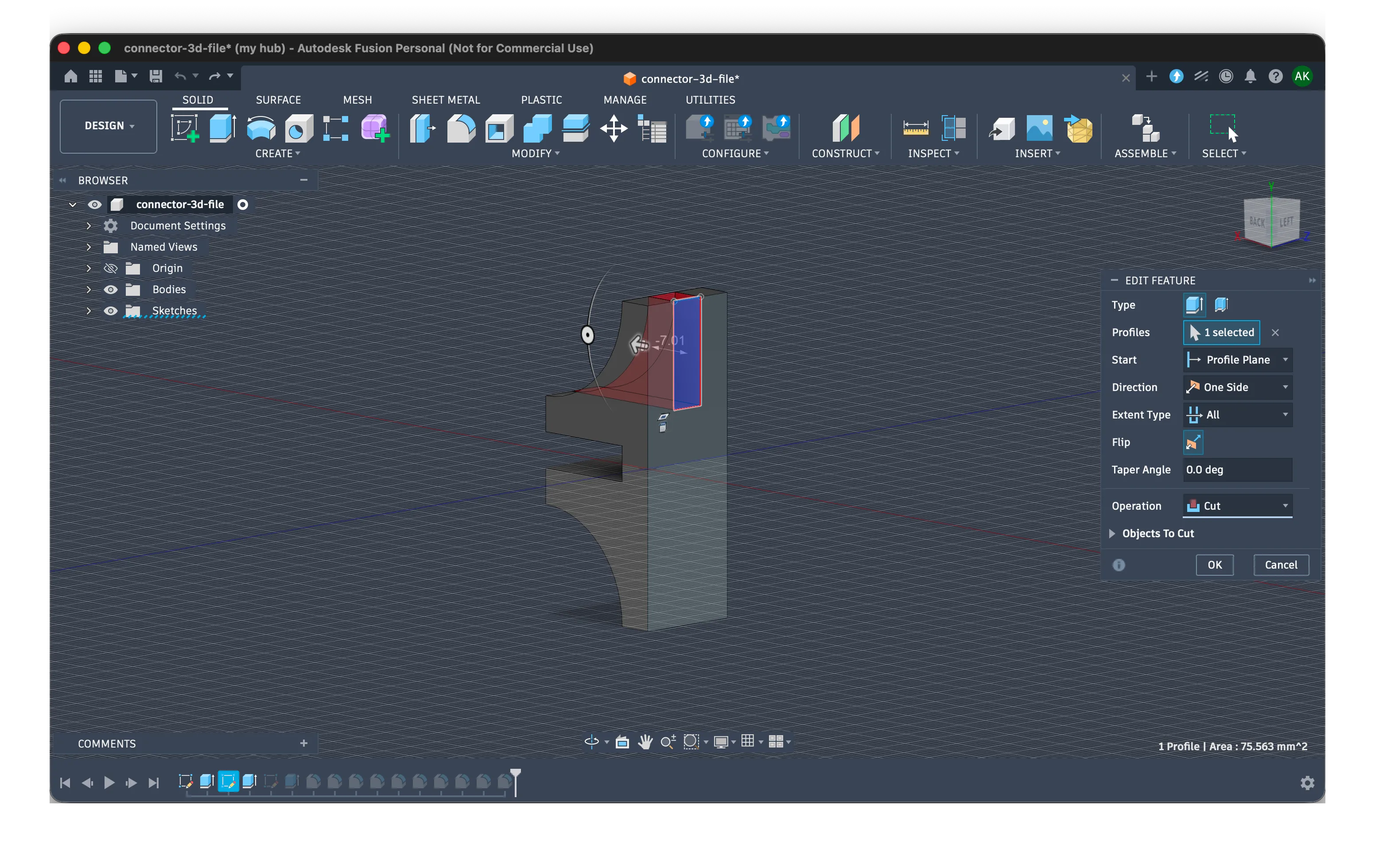
Next step for my model is to add two notches. For that I rotate the model, choose the back face and draw a new sketch on it.
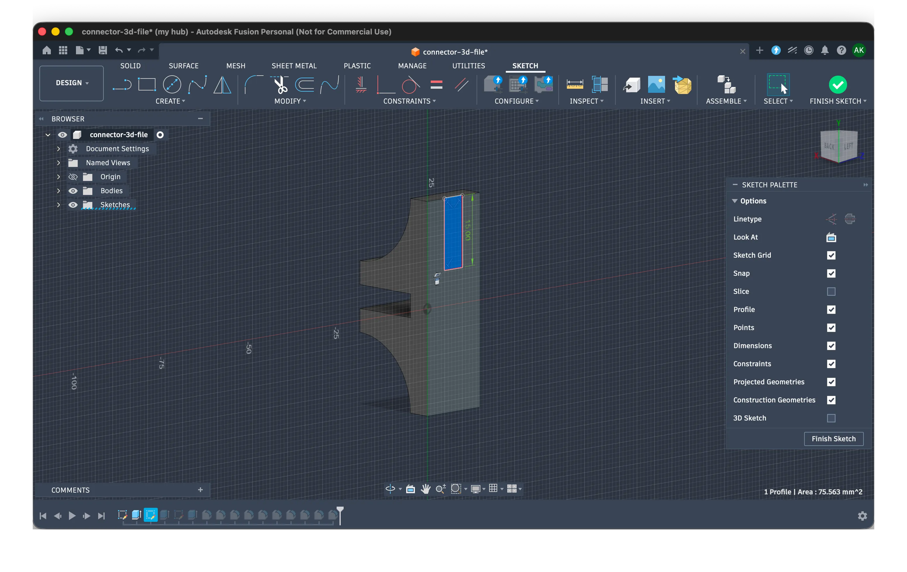
All that is left to do is to extrude it, but this time we change the extrude type to cut! I did it twice to mirror the bottom.
3D model files
A 3D model can be stored in several file formats. The most common formats a beginner will encounter are STL, 3MF, and STEP.
STL is one of the oldest and most common formats used for 3D printing.
An STL file describes the outside surface of an object using many small triangles. It stores the shape, but usually does not store much additional information.
3MF is a newer format designed specifically for modern 3D manufacturing.
One important warning: a downloaded 3MF file may contain someone else’s printer and material settings. Review them instead of trusting them blindly.
STEP files are common in CAD workflows.
Unlike an STL, which stores a surface made from triangles, a STEP file preserves more of the original engineering geometry. This makes it much easier to edit dimensions, holes, curves, and individual features.
I want to add a little texture to the model, and I like how bumpmesh does it, so I exported my model as STL and went there.
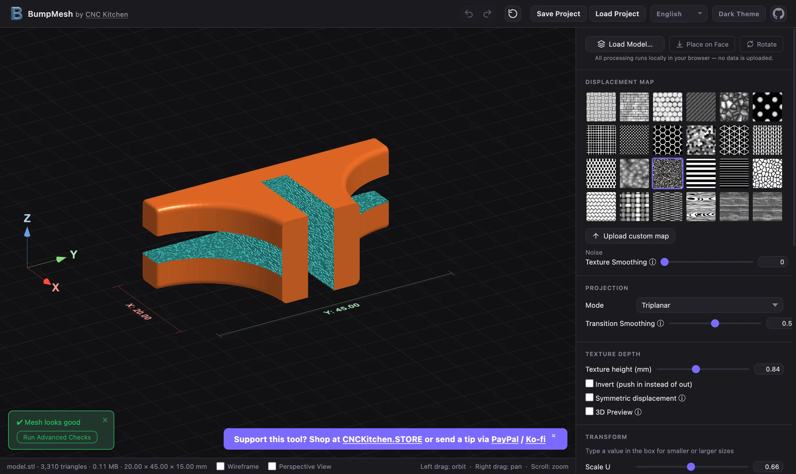
What comes out is just another STL with the texture baked into its triangles. The slicer doesn’t care how a shape was made, only what its surface looks like.
Slicer
A slicer is the program that prepares a 3D model for printing. It cuts your model into layers and works out the path the printer will trace on each one.
It’s also where you decide things like:
-
supports generation
-
wall thickness
-
infill shape and percent
-
layer direction
The slicer then produces a file containing printer instructions. That is called G-code.
G-code
G-code is the language used to control many manufacturing machines, including 3D printers.
A G-code file contains thousands or millions of small instructions.
Conceptually, those instructions say things such as:
Heat the nozzle to 220°C.Heat the print bed to 60°C.Move to this position.Push out this amount of filament.Move to the next position.Increase the height by one layer.Turn on the cooling fan.The instructions look more like this:
G1 X80 Y40 Z0.2 F3000G1 E0.5 F200M104 S220M140 S60G-code player · the connector, layer 1
connector.gcode · edit any number
Layer 1 done. Numbers in, plastic out.
Usually you will not be touching these.
Firmware
Firmware is the software running inside the printer itself.
It receives the G-code and translates it into actual machine behaviour.
The firmware controls EVERYTHING on your printer and usually comes bundled with it.
As a beginner you won’t touch it. Just know it exists, so the word doesn’t scare you when it shows up in update notes, compatibility threads or mod forums.
Host software
Host software provides an interface for communicating with and controlling a printer. These are your Creality Print, Bambu Lab apps etc. Most printers include their own host interface.
And there are two general ways to send a print:
Cloud vs local · same file, different trip
Cloud: computer → maker’s cloud → printer. Local: computer → network, USB or card → printer.
Pick a route, break something, send.
Cloud printing can be convenient, especially for remote access. Local printing gives me more control and does not depend on an external service being available.
Should you care about this now? No.
Hardware
The printer has many components, but you only need to recognize the major ones to get started.
Build plate and print bed
The print bed is the platform the object is printed on; the removable sheet on top is the build plate (or build surface, or print surface). Most beds are heated, which helps the first layer stick and fights warping. Common surfaces: textured PEI, smooth PEI, glass, coated spring steel.
The first layer goes straight onto this surface, so keep it clean. Fingerprint grease makes a surprisingly good release agent.
Extruder, hotend and nozzle
Three parts everyone mixes up, so let’s get them straight:
-
The extruder grips the filament and pushes it.
-
The hotend melts it.
-
The nozzle is the tip the melted plastic comes out of.
The hotend is a whole assembly (heater, temperature sensor, heat block, heat break, heatsink) with the nozzle screwed on the end. People call the whole thing “the nozzle”; now you know better. It matters when filament gets stuck in the nozzle and you have to take the hotend out.
Extruders come in two layouts. Direct-drive sits on the moving print head right next to the hotend, which gives tight control over the filament and makes flexible stuff like TPU much easier. Bowden sits on the frame and pushes filament through a long tube: the print head gets lighter, but floppy filament gets harder to control.
The standard nozzle is 0.4 mm. Smaller means finer detail and slower prints; bigger means faster prints with thicker lines. Brass nozzles handle ordinary filament; abrasive ones with carbon fibre, glass fibre or glow particles need a hardened nozzle, or they’ll chew through the brass.
Filament
Filament is the plastic you feed the printer. It comes on spools sold by weight, usually 1 kg. The ones you’ll meet first:
-
PLA: easy to print, fine for decorative and general-purpose stuff.
-
PETG: tougher and more heat-resistant than PLA, but strings more.
-
TPU: flexible.
-
ABS / ASA: handle heat better, but are harder to print and produce fumes.
-
Nylon: strong and durable, but soaks up moisture like a sponge.
Profiles
A profile is a saved bundle of slicer settings. Three of them work together:
Printer profile+ Filament profile+ Process profile= Sliced print-
Printer profile: the machine. Build volume, bed shape, nozzle diameter, speed and acceleration limits, start/end G-code. The wrong one can mean unsafe movements.
-
Filament profile: the material. Nozzle and bed temperatures, cooling, max flow, retraction. A generic PETG profile is a fine start, but brands, and even colours, behave slightly differently.
-
Process profile: how this object gets printed. Layer height, walls, infill, supports, speed, top and bottom layers. They have names like
0.20 mm Standardor0.12 mm Fine.
For my first print, I selected my printer, chose a generic PLA profile, and used a standard 0.20 mm process profile.
Then the slicer hit me with a wall of terms I didn’t know.
Printing
These are the decisions the slicer makes, or asks you to make, while turning a model into layers.
Layer height
Layer height is the thickness of each horizontal layer. With a 0.4 mm nozzle, 0.12 mm is fine detail, 0.20 mm is the everyday default and 0.28 mm is for when you’re in a hurry. Thinner layers give smoother surfaces, but more layers means more time.
Don’t confuse it with nozzle diameter: the nozzle sets how wide a line is, layer height sets how tall.
Walls, top/bottom layers and infill
The walls (perimeters, wall loops, shell; every slicer picks its own name) are the outer shell. Top and bottom layers close that shell above and below. Infill is the internal structure in between, described as a percentage and a pattern, like 15% gyroid.
Slice preview · 40 × 25 × 20 mm block, PLA
Layer height, mm
100 layers
Rough numbers from a back-of-the-napkin model, not a slicer.
Here’s the part worth remembering: walls beat infill. An extra wall usually buys more strength than cranking up the infill; orientation, material and the direction of the force often matter more. Two walls are fine for decoration; functional parts get three, four or more. 10–20% infill covers most ordinary prints, and 100% is rarely the first or best fix.
Too few top layers and the infill shows through or leaves gaps. Think in millimetres, not layer counts: five layers at 0.20 mm is one millimetre of shell.
Overhangs, supports and bridges
Every layer needs something underneath it. An overhang sticks out without enough material below: moderate ones print fine, steep ones sag or fail.
Supports are temporary scaffolding printed under those parts and broken off afterwards. Normal supports are straight columns: sturdy, but hungrier and touching more of the model. Tree supports branch out, use less material and usually come off easier. Either way they cost time and filament, leave marks, and like to hide in spots your pliers can’t reach.
A bridge is the exception: a span anchored at both ends. The printer stretches plastic across the gap like a rope, and with good cooling and the right speed, short bridges print fine without supports.
Depending on which way the connector lies, the tops of its notches are either a short bridge or no problem at all. Which brings us to orientation.
Less than half underneath. The soft edge sags.
Orientation
Orientation is how the model sits on the build plate, and it’s the cheapest fix you have. Which side faces down changes strength, supports, surface finish, print time and accuracy.
Two rules. Prints are weaker between layers than along them, so orient a functional part for the forces it will take, not for the least filament. And rotating a model into a printable position usually beats smothering it in supports.
Bed adhesion: skirt, brim and raft
Bed adhesion is how well the first layer sticks. Lose it and the print shifts, curls up, or becomes a mass of plastic attached to the nozzle.
The slicer gives you three tools, lightest to heaviest:
-
Skirt: a few lines around the object, not touching it. It primes the nozzle and shows the filament is flowing. It does not really help adhesion.
-
Brim: a flat rim attached to the bottom edge for more contact area. Good for narrow, tall or sharp-cornered parts and warp-prone materials. Peel it off afterwards.
-
Raft: a thick platform under the whole model. More material, more time, a rough bottom. Modern printers rarely need one.
First layer
The first layer is the foundation of the entire print. The nozzle has to be close enough to press plastic onto the bed, but not so close that it blocks the flow or scratches the plate.
Too high: lines stay separate, the print doesn’t stick, corners lift. Too low: the nozzle scrapes, lines come out thin and rough, and flow chokes.
Auto bed levelling helps, but dirt or a wrong nozzle offset can still ruin it.
end-on
from above
Too high: a round thread that won’t stick.
Retraction and seams
When the nozzle travels between separate parts of a print, molten plastic keeps oozing out and leaves stringing: thin plastic hairs between parts. Retraction pulls the filament back slightly before each travel move. Too little strings; too much can cause feeding problems or clogs.
Every wall loop also has to start and end somewhere, and those little marks line up into the Z seam. The slicer lets you choose where it goes (back, nearest corner, random), which matters on decorative prints.
hotend
No retraction: a hair every layer.
Calibration
Calibration means running test prints (temperature towers, flow, pressure advance, retraction and so on) to tune the printer or material.
You don’t need any of it before your first print; the default profiles are a usable start. Calibration earns its keep when you have a specific problem:
-
Stringing → temperature or retraction test.
-
Weak walls → check flow.
-
Rounded corners → pressure advance.
-
Poor adhesion → inspect the first layer and clean the bed.
Calibration should answer a question. It should not become a ritual performed without understanding what is being tested.
Back to the connector
With the vocabulary in place, the whole trip fits in a few lines.
The textured STL from bumpmesh goes into the slicer with my printer profile, a filament profile and a standard process profile. For a functional part like this one I’d go with 0.20 mm layers, three walls, 15% gyroid infill, automatic supports only where necessary, and a skirt.
Press Slice, then actually look at the preview: nothing floating, supports that make sense, enough first-layer contact with the bed.
Send the G-code. The firmware heats the bed and nozzle and works through the instructions line by line. The extruder pushes, the hotend melts, the nozzle lays it down. Walls make the outside, infill the inside, retraction keeps the travel moves clean.
None of it is magic, just a chain of software, files, profiles, hardware, materials and decisions. Once the links have names, and something goes wrong, I can ask a much better question than:
Why does my print look bad?
I can say:
My PETG print has stringing between separate parts. I am using a direct-drive extruder, a 0.4 mm nozzle, and the generic PETG profile. Should I test a lower temperature or adjust retraction?
That is the real value of vocabulary.
It does not immediately make me an expert, but it gives me the tools to learn.
Comments
Comments live in GitHub Discussions (via giscus), so you need a GitHub account to join in.